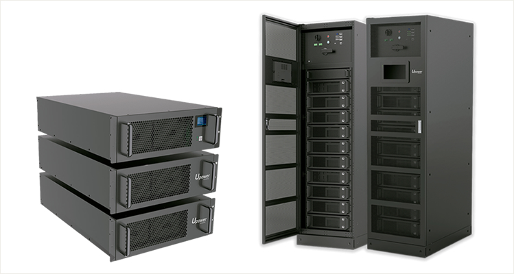
Zero CO2

UE-HP Series

UE-HP Series

UE-HP Series

High Power for UPS Application

Built-in automatic protection for over-charge, over-discharge and exceeding temperature conditions.

One single BMS can manage multiple battery models (<200).

Internal cell balancing.

Thousands of cycles, 100% DOD, under normal conditions.

Can be charged using most standard lead-acid chargers (set for AGM/GEL cells).

System Security Guide

  • Cell Level
    The electric core adopts LFP material system, wich has extremely high safety. In addition, one-way explosion-proof walve is designed on the top. In case of emergency, such as short-time connection outside, the explosion-proof valve can be punched open to cut off the circuit to prevent large safety risks.

  • Module Level
    The temperature control module controlled by BMU at the module level can adjust the temperature in the module in real time to ensure that the operating environment is in a controllable range.

  • Rack Level
    Rack level is mainly through the CBMS internal DC circuit breaker, reply, pre-charge resistance and diode and other power devices, the system to achieve overcharge, over-current, anti-reverse connection and other state management, to ensure the safety and reliability of the rack.

  • System Level
    The main purpose of the system is to control the pressure difference between racks in the parallel machine state, and realize the balance adjustment between racks through pre-charge resistance to ensure the safety of system operation.

SOLUTIONS

+THINK +CONSTRUCT

Battery Monitor System Guide

  • 1. According to the battery modules connected in series after the total voltage is divided into three grades
    U-BMS-LV, 10 ~ 64V (series 4 ~ 16 cells).
    U-BMS-MV, 10 ~ 96V (series 4 ~ 24 cells).
    U-BMS-HV, 96 ~ 300V (series 4 ~ 80 cells).
  • 2. Interface
    The one RS-485 for battery module;
    The other RS-232 with PC or other controller connection;
    The 5 signals "0" or "1" output signal; GPIO1 ~ GPIO5.
    The 2 signals universal input or output port; GPIO6 ~ GPIO7 (standby).
  • 3. BMS power supply
    U-BMS-LV and U-BMS-MV from the string of battery power or the external DC12V power supply; U-BMS-HV built-in 10AH3.6V rechargeable battery, battery charger charging.
  • 4. The power consumption of BMS
    U-BMS-LV and U-BMS-MV: 0.3W ~ 0.8W
    U-BMS-HV: 0.4W ~ 0.6W
  • 5. BMS working mode
    Master mode: the whole battery modules`system managed by BMS, RS-232 for monitoring;
    Slave mode: PC may control BMS to manag battery system used RS-232 to recieve data and send command.
  • 6. The BMS function
    Battery configuration, such as Series or parallel;
    Battery module address management;
    Battery system state judgment: charging, discharging, static;
    RS-485, RS-232 Bus management;
    According to data, control protection switches.

Specifications

Model Nominal
Voltage
(V)
Recommend
Charge Voltage
(V)
Nomimal
Capacity
(Ah)
Max. Cont. Discharge Current
(A)
Dimensions Weight
(Kg)
Data
Sheet
(PDF)
Width
(mm)
Depth
(mm)
Height
(mm)
UE-192Li10HP 192 210 10 50 (5C) 65.3 18.5 150 0.31
UE-192Li20HP 192 210 20 100 (5C) 70.3 19.5 199 0.51
UE-240Li10HP 240 263 10 50 (5C) 65.3 18.5 150 0.31
UE-240Li20HP 240 263 20 100 (5C) 70.3 19.5 199 0.51
UE-240Li50HP 240 263 50 50 (1C) 106 20 308 1,22
UE-240Li100HP 240 263 100 200 (2C) 136 32 282.7 2.35
UE-384Li100HP 384 420 100 200 (2C) 136 32 282.7 2.35
UE-480Li100HP 480 525 100 200 (2C) 136 32 282.7 2.35
UE-512Li100HP 512 100 100 200 (2C) 136 32 282.7 2.35
UE-512V-Li 512 544 50/100 1C@100A/3C @ 300A 800 800 2000 600/695